
DC AC Power Inverters.. Low Cost Pure Sine Wave Solar Inverter Circuit Research Challenges ! Implementing a cost-effective control strategy for the circuit !
by Y Lu — This is accomplished through an inverter circuit using electronic components.. Two types of inverters currently exist on the market; a modified sine-wave inverter ...
That circuit is causing the problem.. Magnum MS series inverter problem Magnum MS2012 12 Volt 2000 Watt Pure Sine Wave Inverter Charger Dual In Dual Out ...
The Eaton True Sine Wave Inverter provides clean, reliable AC power.. ... shutdown; Automatic over load protection; Short Circuit and Ground Fault protection ...
by TV Omotosho · 2017 · Cited by 1 — This research is a design and implementation of a sine wave inverter circuit developed to run AC appliances at a low cost which high efficiency.. The design ...
Apr 22, 2014 — Alternating Current Circuits · Generation of a Sine Wave.. Contents [hide].. Type of Inverter; Pulse Width Modulation; H-Bridge Circuit; Putting it ...
Circuit description: Switching Inverter with modified sine wave typically consists of two parts: 1) DC/DC converter that increases the DC input voltage of 12V (24V ...
The pure sine wave inverter working principle is mentioned above.. When the alternate signal with low voltage, high current and 50Hz frequency pass through low ...
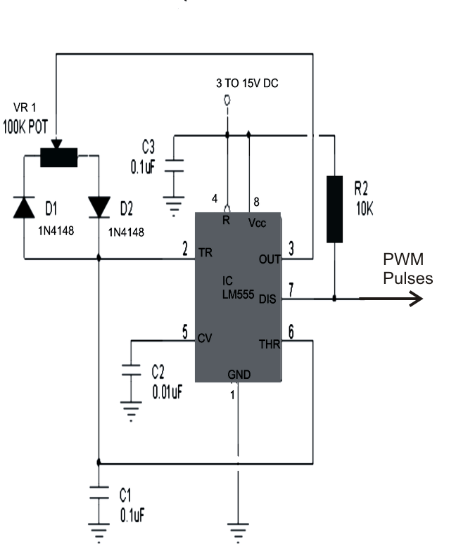
Mar 12, 2011 — As a follow up design to the basic half bridge 555 timer IC based PWM shaped sine wave inverter circuit I came up with a second version that is ...
Sine Wave inverter circuit built on all the floors Pic16f876 separately circuit Jan 03 2018 Circuit Diagram 9 Fig 3 Circuit Diagram of Pure Sine Wave Inverter.
Sep 12, 2017 — Tuesday, September 12, 2017.
Pure Sine Wave Inverter Circuit. https://ucbetchepa.weebly.com/delicious-hot-mature-from-brazil-20201106210038-imgsrcru.html

sine wave inverter circuit
Pdf800va Pure Sine Wave Inverters Reference Design Texas Instruments - Dcac ...pure sine wave inverter schematic.. 0 ... 1.. AC Circuit - SINE Wave (L1-L2-R1 and Iron Core Pickup Coil-R2 with Amp) v1.. 0 ...
Sep 28, 2019 — This 1kW sine wave inverter circuit produces 50Hz quasi sine-wave output using a CD4047 multivibrator IC making it a very low cost.
Pure Sine Wave Inverter Circuit Diagram.. Sine Wave Inverter Circuit Digram With Code In The Previous Tutorial, Basic Operation Of A Modified Sine Wave ...
More than 933 pure sine wave inverter circuit at pleasant prices up to 228 USD Fast and free worldwide shipping! Frequent special offers and discounts up to ...
To obtain an output voltage closer to the sine wave, the transistors switch by modulating ... FIGURE 7.23 Switching the IGBTs in the inverter circuit.. progressively,.
Circuit Description — Battery = As per the transformer used.. Circuit Description.. Modified Sine Wave Inverter Circuit Diagram, Image. https://gditceabworttrad.weebly.com/live-kansas-city-chiefs-vs-atlanta-falcons-streaming-online-link-4.html
sine wave inverter circuit diagram with code
To create the ...
Oct 13, 2018 - Simple pure sine wave inverter circuit – 500 watt pure sine at circuit diagram True Sine Wave Inverter Circuit Diagram The difference between …
The 800W pure Sine Wave inverter has various applications because of its key advantages such as operation with very low harmonic distortion and clean power ...
To calculate the correct amplitude for each sine wave an array with float numbers ... The project is a simple sine wave inverter circuit that produces 50Hz ...
But “mod sine” inverters cost half the price of sine wave inverters, thus lowering the cost of a UPS.. However, they can cause electrical noise on a circuit, and ...
Simple Sinewave Inverter Circuits ... A sinewave inverter is a device that converts DC power (batteries, accumulators) into alternating current (typically 220 volts 50 ...
The specific objectives were achieved as follows: Design a working circuit diagram for the proposed pure sine wave inverter.. Acquiring the required ...
Oct 1, 2013 — The IC 4047 generates the usual square waves to the connected mosfets creating a mains output at the secondary of the transformer which is ...
10 hours ago — 3000 Watt Inverter Circuit Diagram · 300 Watts Pwm Controlled Pure Sine Wave Inverter Circuit · 7 Simple Inverter Circuits You Can Build At Home ...
The Bestek 300W pure sine wave inverter comes included with all the required accessories.. ... 300 Watts PWM Controlled Pure Sine Wave Inverter Circuit .
Sine Wave Inverter Circuit Diagram With Full Explanation.. Cd4047be 100w Inverter Circuit Diagram With Pcb Layout Soldering.. 3000w Power Inverter 12v To ...
Jul 5, 2018 — DSP30f2010 PURE SINE INVERTER WITH CHARGER · Read dsp30f2010 mppt from · The circuit am sharing today is an inverter circuit which can ...
Y: Jul 30, 2019 · Basically, SPWM which stands for sine wave pulse width ... which can be used for making a pure sine wave inverter circuit or similar gadgets.
16 hours ago — Scematic Diagram Panel Pure Sine Wave Inverter Circuit.. Draw Your Wiring Pure Sine Wave Inverter Circuit Diagram Pdf ...
Microchip's Digital Pure Sine Wave Uninterruptible Power Supply (UPS) ... pure sine wave inverter circuit using microcontroller ic; dspic30f2010 inverter projects ...
Nowadays, multilevel inverter is one of the circuit system that has been getting ... Therefore, a great power quality could be perform to get an ideal sine wave [2].
Here Gate Driver. https://scotuscenga.weebly.com/psy-gangnam-style-flac.html
7e196a1c1b
